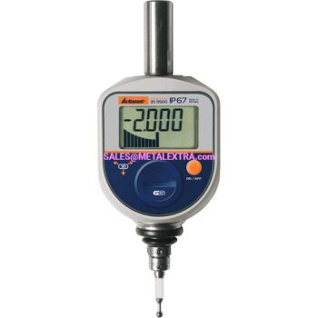
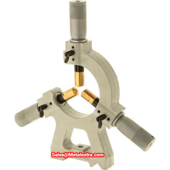
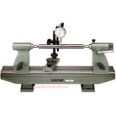
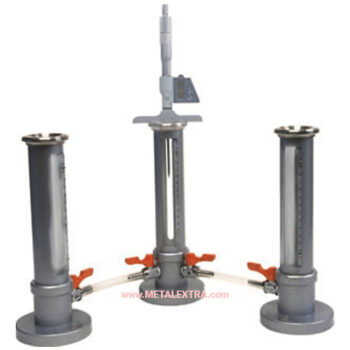
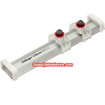
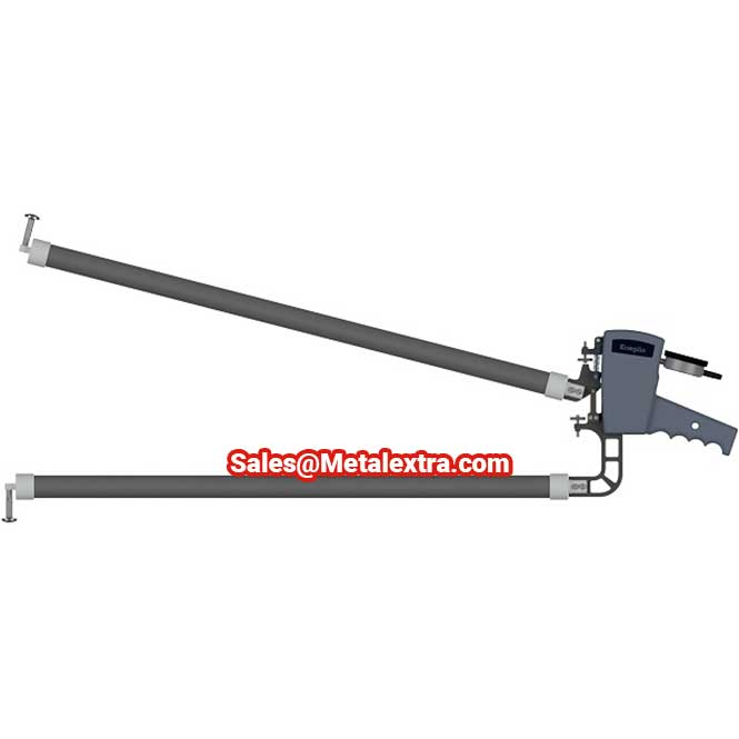
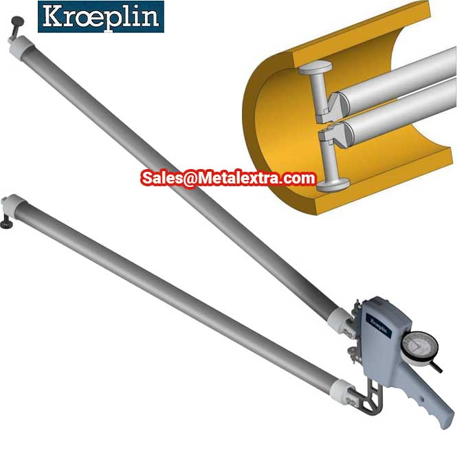
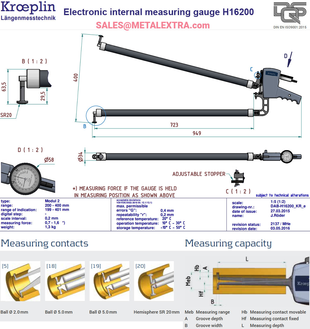
Dimensi KROEPLIN Internal Measuring Gauge H16200 Series ⌀200mm – ⌀400mm:

Order Guide KROEPLIN Internal Measuring Gauge H16200 Series ⌀200mm – ⌀400mm:
| Type |
H16200 |
| Display mm / inch |
mm |
| Application |
Internal measurement |
| Measuring span Mes |
200 mm |
| Measuring range Meb |
200 – 400 mm |
| Range of indication Azb |
199 – 401 mm |
| Scale interval Skw |
0,2 mm |
| Max. permissible errors G |
0,4 mm |
| Repeatability limit r |
0,2 mm |
| Measuring force F min. |
0,7 N |
| Type of measuring contact movable |
Hemisphere SR 20 mm |
| Measuring contact movable Hb |
29,5 mm |
| Type of measuring contact fixed |
Hemisphere SR 20 mm |
| Measuring contact thickness max. |
20 mm |
| Measuring depth max. L |
746 mm |
| Weight |
1300 g |
| Reference temperature |
20 °C |
| Reference temperature |
10 – 30 °C |
| Storage temperature |
-10 – 50 °C |
| Protection class |
Not available |
| Interface Digimatic |
Not available |
| Interface USB |
Not available |
| Wooden box |
HK |
Alternative Guide for KROEPLIN Internal Measuring Gauge H16200 Series ⌀200mm – ⌀400mm:
| Type |
Measuring Span Mes |
Measuring range Meb |
Range of indication Azb |
Numerical interval Zw |
Max. permissible errors G |
Repeatability limit r |
Measuring force F min. |
Measuring force F max. |
weight |
Protection |
Measuring contact movable Hb |
Measuring contact fixed Hf |
Type of measuring contact fixed |
Groove Depth A max |
Groove Width B Min |
Measuring Depth L Max. |
Electronic Emechanical M |
Wooden box |
| Code No. |
[mm] |
[mm] |
[mm] |
[mm] |
[mm] |
[mm] |
[N] |
[N] |
[g] |
|
[mm] |
[mm] |
[mm] |
[mm] |
[mm] |
[mm] |
|
|
| G4100 |
50 |
100–150 |
99.5–150.5 |
0.02 |
0.06 |
0.04 |
1.0 |
1.8 |
425 |
IP67 |
8.5 |
8.5 |
Ball Ø 2 |
8.3 |
2.4 |
192 |
E |
1732-51 |
| H4100 |
50 |
100–150 |
99.5–150.5 |
0.05 |
0.05 |
0.025 |
0.9 |
1.9 |
385 |
IP65 |
8.5 |
8.5 |
Ball Ø 2 |
8.3 |
2.4 |
192 |
M |
1732-51 |
| G4130 |
50 |
130–180 |
129.5–180.5 |
0.02 |
0.06 |
0.04 |
1.0 |
1.8 |
430 |
IP67 |
8.5 |
8.5 |
Ball Ø 2 |
8.3 |
2.4 |
192 |
E |
HK |
| H4130 |
50 |
130–180 |
129.5–180.5 |
0.05 |
0.05 |
0.025 |
0.9 |
1.9 |
390 |
IP65 |
8.5 |
8.5 |
Ball Ø 2 |
8.3 |
2.4 |
192 |
M |
HK |
| G4150 |
50 |
150–200 |
149.5–200.5 |
0.02 |
0.06 |
0.04 |
1.0 |
1.8 |
435 |
IP67 |
8.5 |
8.5 |
Ball Ø 2 |
8.3 |
2.4 |
192 |
E |
HK |
| H4150 |
50 |
150–200 |
149.5–200.5 |
0.05 |
0.05 |
0.025 |
0.9 |
1.9 |
395 |
IP65 |
8.5 |
8.5 |
Ball Ø 2 |
8.3 |
2.4 |
192 |
M |
HK |
| G850 |
100 |
50–150 |
49.5–150.5 |
0.05 |
0.15 |
0.1 |
0.8 |
2.0 |
650 |
IP67 |
4.0 |
4.0 |
Ball Ø 5 |
3.0 |
5.5 |
395 |
E |
HK |
| H850 |
100 |
50–150 |
49.5–150.5 |
0.1 |
0.15 |
0.1 |
0.8 |
2.0 |
590 |
IP65 |
4.0 |
4.0 |
Ball Ø 5 |
3.0 |
5.5 |
395 |
M |
HK |
| G870 |
100 |
70–170 |
69.5–170.5 |
0.05 |
0.15 |
0.1 |
0.8 |
2.0 |
650 |
IP67 |
14.0 |
14.0 |
Ball Ø 5 |
13.0 |
5.5 |
395 |
E |
HK |
| H870 |
100 |
70–170 |
69.5–170.5 |
0.1 |
0.15 |
0.1 |
0.8 |
2.0 |
590 |
IP65 |
14.0 |
14.0 |
Ball Ø 5 |
13.0 |
5.5 |
395 |
M |
HK |
| G1290 |
100 |
90–190 |
89–191 |
0.1 |
0.3 |
0.1 |
1.0 |
1.5 |
910 |
– |
13 |
13 |
Ball Ø 5 |
12 |
5.5 |
535 |
E |
HK |
| H1290 |
100 |
90–190 |
89–191 |
0.1 |
0.3 |
0.1 |
1.0 |
1.5 |
950 |
– |
13 |
13 |
Ball Ø 5 |
12 |
5.5 |
535 |
M |
HK |
| G12150 |
100 |
150–250 |
149–251 |
0.1 |
0.3 |
0.1 |
1.0 |
1.5 |
920 |
– |
30 |
30 |
Ball Ø 5 |
29 |
5.5 |
535 |
E |
HK |
| H12150 |
100 |
150–250 |
149–251 |
0.1 |
0.3 |
0.1 |
1.0 |
1.5 |
960 |
– |
30 |
30 |
Ball Ø 5 |
29 |
5.5 |
535 |
M |
HK |
| G16200 |
200 |
200–400 |
199–401 |
0.2 |
0.4 |
0.2 |
0.7 |
1.6 |
1200 |
– |
29 |
29 |
Hemisphere SR 20 |
28 |
21 |
720 |
E |
HK |
| H16200 |
200 |
200–400 |
199–401 |
0.2 |
0.4 |
0.2 |
0.7 |
1.6 |
1300 |
– |
29 |
29 |
Hemisphere SR 20 |
28 |
21 |
720 |
M |
HK |

